DXpedition Pileup Management

Pileup Management

The WeeklyDX™ Helpful Hints No. 35 from the DX University™*

Best Practices for DXpedition Operating

This week, I want to address DXpeditioners directly. DXpeditions during the past few months have been a problem. To be honest, some of the operating has been very poor. (That’s a polite version of what I have been reading.)

Some of the DXpedition operators recruited for these operations seem to have forgotten – or never learned – much of what has been written about how to manage their operations. As a result, reactions to these operations in many cases have been vile. Much of the negative reaction is coming from DXers who see their opportunities for a QSO diminishing. Additional reaction is coming from non-DXers who have had their own operating unnecessarily disrupted by the pileups. In these cases, the non-DXers have gone to the source, the DXpedition frequency. Setting off a circus there is not difficult at all.

There have been numerous attempts in the “local media” to pinpoint the reasons for this behavior, and some of it has been off the mark. But increasingly, DXers are beginning to understand: virtually every instance of poor pileup behavior can be attributed to poor pileup management. The nature of a DXpedition pileup mirrors the skill of the DXpedition operator. A carefully managed pileup will run with little disruption to the remainder of the band and minimize frustration. To begin, here are some suggestions for making the most of your pileup.

Best Practices for DXpedition Operating

1. Check your transmit and receive frequencies before starting.
2. Use split operation from the beginning
3. Maintain a rhythm of regular transmissions. No long silences.
4. Do not use excessive speed on CW. Slow down when signals are weak.
5. Reduce speed further on CW to communicate with the pileup.
6. Sign your call sign at least every minute.
7. Issue calling instructions after every QSO: EU UP5 or NA UP 5-10
8. Minimize Pileup width: Suggest Max 5kHz CW and 15kHz SSB.
9. Move receive frequency in a generally regular pattern.
10. Repeat corrected call signs so everyone is confident of being correctly logged.
11. Work and log dupes, it’s quicker.
12. Don’t leave the pile-up hanging: Keep the callers informed about QRT/QSY, etc.
13. Maintain a moderate, but “in-charge attitude.”

*This list, and more about these Best Practices will appear on the pages of the DX University very soon.

In the remainder of this space today, I will mention two of these points. The first is point number 8. Several DXpeditions have been observed working stations on the “WARC” bands over virtually the whole range of frequencies. This is simply unacceptable, and really unnecessary. The DX operator who says he can’t hear without spreading the pile so widely frankly hasn’t learned how to manage his pileup. The suggested limits are and must be adequate – by definition. The bands don’t belong solely to DXers. To believe that they do is nothing if not arrogant. If there are too many stations calling within those limits, steps must be taken to limit the number of stations calling. Roger, G3SXW points out:
http://dx-code.org/DXpednew.html#split

As responsible [DXped] operators, be considerate of other users. It’s their band too. The more rare the DXpeditions QTH, the larger the likely pileup and this can produce pileups that spread out beyond what is reasonable. A 5 to 8 KHz spread for CW and 10 to 15 KHz spread for SSB are considered by many DXpedition operators to be reasonable.

Roger adds: Additional good reading on this topic can be found at http://www.dxuniversity.com/dxped/tools.php

Another important practice is Point #12: not to leave the pileup hanging. There has been considerable complaining about DXpedition stations moving from their frequencies without notice, etc. If a QRX or QSY to another band is necessary, inform those DXers in the pileup. We all know that frustration is a primary catalyst for chaos. Considerable frustration can be avoided by being careful to let the callers know what you plan to do.

Of course, there are other exacerbating conditions. In particular, some expeditions to very rare places don’t have the resources to match the rarity of their location. I believe the PT0S expedition to St. Peter and St. Paul Rocks is one of these. This is basic and conceptual planning. PT0S a “specialty DXpedition,” concentrating on the low-bands and on six meters. This expedition was billed as a specialty event, but that seems to have gone unnoticed. With only four operators, this leaves one operator responsible for impossible task of meeting the demand on all of the other bands. It is likely that SP&P is just too rare for four operators and a concentration on the low bands and six meters. As a result, the callers are spread over fewer bands, increasing the demands on the pileup management skills of the operators. My observation is that the low band pileup management is excellent, while the operation on the other bands leaves something to be desired.

*The DX University™ is a daylong learning session for newcomers and old-timers wishing to hone their DXing skills. These weekly articles published in the WeeklyDX™ are archived in the pages of The DX University.

Thanks to the DX University and the WeeklyDX™

Back to top^

Posted: 2012-11-18

ZM4T CQWW CW 2012

I don’t know what it is about contests, but they seem to take on a life of their own for 48 hours. Each contest is different in nature and operation. This one was a cracker because every facet just seemed to come together and the contest “worked”

At the end of the CQWW SSB test a month ago there was little enthusiasm to do the whole thing on CW again. A week later, Gary and I had a change in heart and decided to do a Multi-Two which grew into a Multi-Multi over a few weeks when ZL3IO became available. Gary then persuaded John ZL1BYZ from Auckland to join us and it was all on.

A multi-multi computer setup is quite different than M2. More equipment, more antennas are needed along with more ops. In the end, Gary ZL2iFB, Holger ZL3IO, John ZL1BYZ, Michael ZL2MY and I took on 48 hours with little sleep and a target score to aim for.

In the past, the ZM1A and ZL6QH teams have been hard to catch with formidable records that have lasted for many years. Could we catch them?

Gary ZL2iFB

John ZL1BYZ

Michael ZL2MY

Holger ZL3IO

Lee ZL2AL

Friday Morning

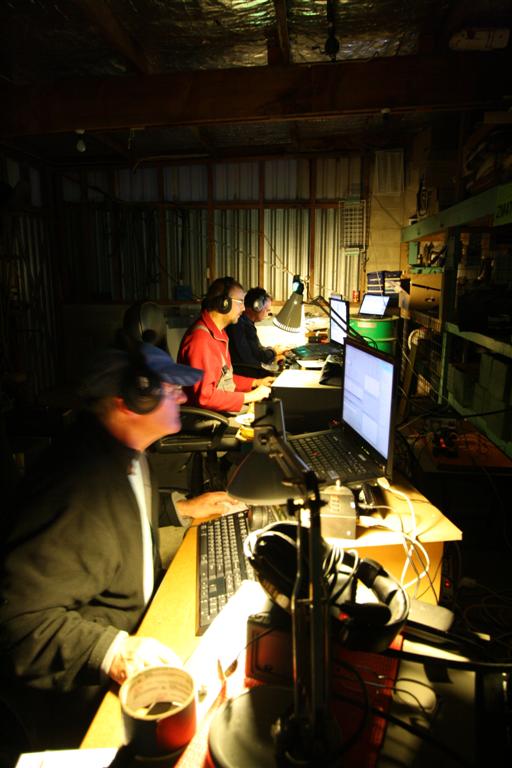
Gary and Lee started into setting up the three operating stations. The radios, amplifiers and laptops were placed and networking was set up with N1MM contest logger and fed with a 4th laptop to give us spots from the internet DX Clusters. We have the luxury of having 3el on 20m, 5el on 15m and 4el on 10m with loops for 80 and 40 metres permanently in place so it’s a simple matter to connect the stations to any antenna needed at the time.  Strangely, everything worked as it should and we were ready to go Saturday morning.

Saturday

Lee arrived to find Gary and John attempting to make some Russian carbon ceramic resistors he purchased on eBay into a single 600 ohm resistor pack.

“Unibomber” Lee and the 2 x 600 ohm terminating resistor packs

VEE Beam with open wire feeders. The two 100 metre legs out to the right.

Gary decided that we needed a Vee beam with 100 metre legs pointing out to sea towards NA. The Vee beam needed terminating resistors. Time was marching on so Lee put a line over a tall pine with the infamous ZM4T spud gun and took over the fiddly soldering job while Gary and John ran out the antenna.

The 80m Spiderpole Vertical

Holger arrived and quickly got to work setting up his 18 metre Spiderpole which is our ¼ wavelength vertical on 80m. The 40m vertical on the roof of the big shed was soon in place and all was ready for a 0000 UTC start.

We opened the contest with an excellent start rate and it just went on and on. 10m and 15m were running hot. 20m woke up around 0200 hours. 6 hours of operation put 1400 QSOs in the log and over a million points. 12 hours in and we were at 2900 contacts and 3.3 million points.

Our tracking chart indicated a target of 8,000 was possible if we could hold the rate. Gary’s new THP HL2.5 Amplifier performed very well indeed. The LCD panel readout shows the internal temperature.

40C degrees and running cool!

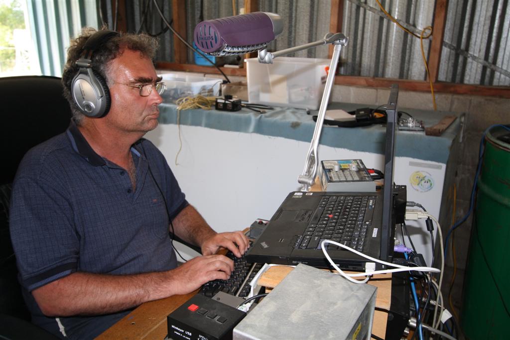
Long productive runs barely moved the temperature up 5 degrees.The problem was there were only 4 of us to operate 3 stations. Michael, ZL2MY arrived Saturday night for the weekend which gave us a bit more flexibility. I noted that all operators would operate for up 13 hours without sleep and only a few tea breaks.

Sunday

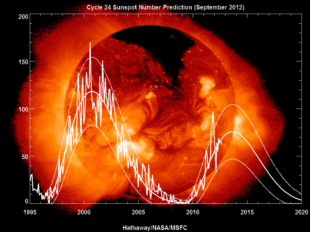
At breakfast our total was around 3800 contacts and 5 million points. Tracking indicated we would reach our target around 10 hours before the finish.Gary’s “multiplier bells” were constantly ringing. The strain was showing on the operator’s faces as they had only managed a few hours sleep since the contest start. Band conditions were deteriorating and extreme solar events were happening. 10M was a good example of this phenomenon. During a productive run and without warning the rate would drop off radically and then dwindle to nothing. 20M was producing thin, watery signals at times which made copy difficult.  John mentioned seeing multiplier spots on 40M during the greyline while the three stations were fully booked on 20, 15 and ten meters. His suggestion of setting up a fourth setup dedicated to 40M was taken up. We set up a spare FT1000MP Mk5 and a Drake amplifier. Gary set up his laptop on the network ready for action Sunday greyline time. It was a good chance to experiment.

“In The Middle of The Night” (apologies to Billy Joel)

Sunday turned into a long hard slog as fatigue set in. Lee went home Sunday evening and upon returning Monday morning looked at the figures on N1MM in disbelief as we had passed the ZL6QH and ZM1A record with 14 million points and another 6 hours to go. Monday morning is difficult as only the scraps remain. There are few stations you haven’t worked and endless CQing, followed by chasing frustrating multipliers that are just above the noise on the other side of the planet. You can hear them but they are focused on working 599 signals they can work easily. ZL is not a priority. Still, there were successes with a few more rare multipliers in the log. The contest ended with a raw score of 8363 QSOs and 16,493,588 points showing on the N1MM screen. The contest organizers at CQ undoubtedly will reduce that score by a significant amount due to logging errors on our part and also will attribute errors to the stations we worked. It is inevitable that errors occur and every team tries to minimize them and maintain a high degree of accuracy but errors do happen.

Gary with VEE Beam in hand

Monday 0000 Utc rolled around and the contest ended. Everyone pitched in as usual and soon all the equipment was back in the boxes. Antennas were taken down and packed away. The usual post contest “around the table” meeting showed that most things went well with virtually no gear failures and antennas performing well. Internet for a solid 48 hours was a bonus. We have never been able to achieve that from our location. Contest teams are successful because of decisions made during the contest by the individual operators. The importance of knowing when to turn an antenna as the propagation changes cannot be underestimated. Knowing when to cut your losses as a run dwindles away and to look for multipliers defines a good op.

The line of Pine trees at the back of the shack supports the 80m & 40m
full size loops and our full size 160m vertical with above ground radials

Location, location, location! You can have great ops, the latest equipment and lots of aluminium high up but if you don’t have a quiet site well above sea level it is hard to be competitive. The ZM4T site is about 20 miles north of Napier back in the hills about 1 km from the sea and 120 metres above sea level in a totally rural area with no noise. It is a superb location to run a contest from. Loud and clear signals from all over the world just pop out without actually registering on the S-Meter.

Equipment logistics and organization of which ops to put on which bands will affect the overall team’s performance. It goes without saying that the very best in equipment and antennas will contribute to the team’s success. This is limited by the team’s finances of course. We need more CW ops if we are to maintain a presence in the Multi-Multi category. Other quality CW ops may have to be seconded to our group, perhaps from out of the area. After some discussion of possible names we were surprised by the lack of ZL contest CW operators actually available in ZL. Perhaps CW is a dying art?.

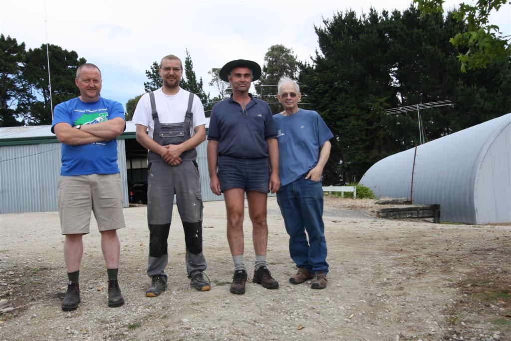
The Team! L to R – ZL2iFB ZL3IO ZL1BYZ ZL2AL

We all had a great time. Personally, it was the best weekend of contesting I have ever had. It was a lot of fun to hang out and just enjoy the intensity. I can’t help but admire and respect the dogged determination and dedication of every member of the ZM4T Team. They all appear so relaxed while on a tea break. When the break is over their utter concentration hour after hour is amazing. Contests are not only about the operating. There is the social aspect of working together for a common cause and achieving it. Male bonding perhaps? In any case we are looking forward to the CQWW WPX in March 2013. As they say “See you in the pileups!”

73, Lee ZL2AL

Back to top^

DX Code Of Conduct

From The Northern California DX Foundation

You may have heard about the DX Code of Conduct (www.dx-code.org), but you might not know its history or the current state of the project. The genesis was DX Etiquette, an article that appeared in  QST  early in 2010. It aroused a groundswell of support and people asking, “Why can’t we do something about it?” So we did. A small committee of world renowned DXers got behind the idea of developing suggestions about how to promote ethically based operating.

These were not new; in fact The Amateur’s Code (Creed) was formulated in 1928. ON4UN and ON4WW even wrote a book about it. We wanted to revitalize the concept of good sportsmanship and carry that message to every DXer in the world. Accordingly, our first objective was to translate the code into other languages, currently 35, enough so that every operator can find it in a language he can read. At the same time, we spread the word to the various clubs around the world. Our next objective was to get the DXpeditions on board. After all, as pileup behavior improves, the DXpedition operators are the prime beneficiaries; they have more fun. The same holds true with the DXers at the other end. Operators returning home tell us we are making a difference. We also want to help every DXpedition operator become fully proficient in pileup management skills.

We have received help from Hams who have been on many DXpeditions who have helped create a portion of our website with suggestions that every team leader can use for training newer operators. Promoting ethics isn’t the easiest of tasks. In fact, it can seem rather stuffy, as if we are preaching to people. The term “good sportsmanship” seems easier to swallow than ethics. We hope each operator will see the logic and say, “That’s what I believe too.” With that attitude comes support, and with that support the Ham radio community will be the beneficiary.

The Code

  • I will listen, and listen, and then listen again before calling.
  • I will only call if I can copy the DX station properly.
  • I will not trust the DX cluster and will be sure of the DX station’s call sign before calling.
  • I will not interfere with the DX station nor anyone calling and will never
  • tune up on the DX frequency or in the QSX slot.
  • I will wait for the DX station to end a contact before I call.
  • I will always send my full call sign.
  • I will call and then listen for a reasonable interval. I will not call continuously.
  • I will not transmit when the DX operator calls another call sign, not mine.
  • I will not transmit when the DX operator queries a call sign not like mine.
  • I will not transmit when the DX station requests geographic areas other than mine.
  • When the DX operator calls me, I will not repeat my call sign unless I think he has copied it incorrectly.
  • I will be thankful if and when I do make a contact.
  • I will respect my fellow hams and conduct myself so as to earn their respect.

Back to top^

Station Grounding

Will we ever be able to dispel the myths?

This is a much beaten-up subject. Hardly a day goes by that on some ham radio board or reflector there isn’t a question about “station grounding.” Funny part is, the subject’s been so discussed, that anyone asking a question must have not been paying attention for the past several (fill in: days, weeks, months, years).

Problem

I think the biggest problem is that a lot of commercially manufactured equipment comes complete with a “ground terminal,” usually somewhere on the rear of its chassis. That, along with directions from the equipment manufacturers, implies the equipment owner ought to connect something to it.

I view this as an adjunct to the “SWR” dilemma. You know, the one that drives hams crazy believing that for an antenna to work properly it must have a low SWR. Or, sillier still, that an antenna with a low SWR must be working properly.

It’s funny that before about 1960, few hams owned an SWR measuring instrument of any sort but somehow made DXCC, bounced signals off the moon, worked meteor scatter, aurora and E-skip, and just happily made contacts without having the foggiest idea what their antenna’s SWR was. Commercial transmitters didn’t have internal SWR bridges, and inexpensive bridges weren’t on the market. The famous “Monimatch” circuit hadn’t yet been published, so few hams knew how to build an SWR bridge, nor would they bother trying. Hams, and their transmitters, were perfectly content to be working each other, around the world, without this fabulous knowledge.

Now, back then it was also pretty common for a lot of equipment to not even have a ground terminal. Some of it did, some of it didn’t, and it didn’t matter much one way or the other. I think the best reason for a ground terminal would have been to help prevent equipment users from killing themselves due to internal short-circuits in equipment that was AC powered, back before 3-prong (and 3-wire) power cords, plugs and outlets became common.

Ironically, the most unsafe equipment back in those days was thousands – if not millions – of inexpensive, AC-line powered broadcast radios, including bedside “All American Five” type radios and clock radios, which did not use AC line isolation transformers. To minimize production cost, a lot of these radios directly rectified the AC line and fed a full 120 volts AC to a series string of tube filaments. The string totalled around 120 volts, so no filament transformer was needed. One side of the AC mains was connected directly to the radio chassis (preferably, the “cold” side of the mains!), and to prevent people from touching the chassis, the little radios were installed in plastic enclosures and used plastic knobs over the control shafts. These radios did not have 3-wire power cords.

Those were accidents waiting to happen, of course. Untold thousands of people received electrical shocks from these radios, and they were responsible for more than a few fires. Sadly, some probably lost their lives due to such shabby design.

And while those radios really indicated an actual need for a chassis (earth, safety) ground, they didn’t have any provision for one.

But we don’t use radios like that any more. Now, we have equipment that uses isolation transformers, and 3-wire power cords plugged into grounded outlets. And a lot of our equipment is powered by low voltage DC, where a shock hazard is literally nonexistent. (You can be hurt by low voltage DC, but not electrocuted. The major source of injuries to people working with low voltage DC is in the form of burns caused by jewelry shorting out the DC power supply’s output bus, which can often pump dozens of Amperes through a ring or bracelet before shutting down – if it ever shuts down.)

So, why do we ground?

Really good question. I guess I’d preface my answer with this simple statement:

I’ve been a licensed ham for 39 years, and continually active. I run legal-limit amplifiers and power output on 160 meters through 10 meters, a kilowatt on 6 and 2 meters, and a couple hundred watts on 135cm and 70cm, and sometimes on 33cm and 23cm, too. I’ve used dozens of different antenna configurations and have operated from all over the world, but mostly from any of the fifteen home-station hamshacks I’ve built over the years at the various homes I’ve owned.

And in all that time, I’ve never once had a “station ground” of any sort.

And in all that time, I’ve never had any problem that grounding would solve.

I’ve operated mobile, marine mobile, maritime mobile and aeronautical mobile and never had a ground on any of these vehicles, either. Especially when operating from an aircraft, that’s hard to do. I’ve also set up dozens of field operations, including Field Day and other contests, without ever owning a ground rod or feeling the need to drive one in, anywhere.

Therefore, you can see I’d be a tough one to convince that a “station ground” serves any particular purpose. Not to say it cannot help, in some situations. But in most all those situations, better station engineering would help more.

(For clarification: Nowhere in this article will I say it’s a bad thing to ground your equipment. I just discuss the counterpoint, that grounding your equipment usually isn’t necessary, and if you’re spending any time deliberating on this issue, that’s time wasted that you could be operating, instead.)

RF Grounding

There’s surely such a thing, and it’s a good thing. If I ever use a voltage-fed antenna or a random wire, I usually place my antenna tuner outdoors, or at least in an open window, so the entire antenna is literally outside, and then I have a very short and direct path to Mother Earth for the return current. The earth completes the current path from transmitter to antenna and back, and everything is happy. This is a great situation. But you really need to have the tuner laying on the ground, or very darned close to it, to accomplish this feat – because a tuner sitting on a desk in the shack is often too far from ground to be effectively grounded.

Usually, however, I use current-fed antennas and I match the antennas to their transmission lines (by adjusting the antennas themselves). Most of my lines are coaxial cable, but some are twin lead. If I use coax to feed a balanced antenna, I use a current balun at the antenna feedpoint. If I use twin lead to feed a balanced antenna, I don’t need a balun, except perhaps in the shack where I transition to 50 Ohm equipment. In all cases, the lines are cool and quiet and don’t seem to bring any RF back “down the pipe” from antenna into the shack.

That’s the result of matching, choking and cable routing to minimize this problem. That not only works better than grounding the station equipment, but it’s also easier to accomplish, usually.

It’s true that most antenna designs won’t provide a good match over more than maybe 2% of the operating frequency. So what? My 80 meter inverted vee is resonant at 3.750 MHz, and its SWR rises to >3:1 at both band edges (upper and lower). Yep, that’s about 25% reflected power. Okay, I’ll repeat: So what? I use my amplifiers as antenna tuners, can transfer all the power generated to the load just fine, and have zero RFI, RF “feedback,” or other problems. No “hot mikes,” no burns from accessories, no nothing, nada, zip. The secret is station engineering. That is, my antennas are located sufficiently far from my equipment that very little radiates back into places I don’t want it to be. And, I do use current baluns in the form of coaxial RF chokes and the like; and, for stubborn cases (especially on the very lower frequency bands, where it’s difficult to escape the antenna’s near field) I use ferrite isolators on the feedlines, installed just outside the shack wall.

I obviously don’t need any station “RF ground,” and never made any attempt to have one.

Lightning

I live inLos Angeles, which has the lowest incidence of lightning strikes of anywhere in theU.S.(fewer than 5 lightning incidents annually on average, and that’s recorded in the mountains or high desert, not where I live). But, it doesn’t matter. I grew up inNew Jersey(70+/year) and have lived inFlorida(90+ but it seems like a million), and have operated from many tropical places where lightning is so common that people miss it if it doesn’t happen daily.

Fact is, grounding your equipment chassis inside your home doesn’t do anything to prevent lightning damage, anyway. The last place you want lightning energy to find a path to earth is inside your home. The only place you want lightning energy to find a path to earth is outside your home. Volumes have been written on this subject by people more knowledgeable than I, so I’d refer you to those volumes for more information.

The only thing I’ll say is, “Equipment (chassis) grounding is not helpful with regard to lightning protection.” And that fact ought to be self-evident to anyone who understands electricity.

Safety ground?

As I mentioned earlier, there are very valid reasons for “safety” grounding, although I’ve never once had an equipment fault that would have caused a safety concern whether the equipment was grounded, or not. But, it’s possible. And, it’s the reason that all construction in the past 30+ years inAmerica(and many other places) used 3-wire grounded outlets throughout. The third (green, ground) wire should be connected to the ground buss in the building’s electrical service panel, which should be grounded directly to earth via an 8′ ground rod driven into earth at the nearest practical location, usually directly under the panel.

It’s possible that even this excellent protocol can fail, but it’s rare. In the event it does fail, a secondary earth ground for station equipment is a “belt and suspenders” approach that probably can’t hurt. I must say, though, that having owned hundreds of pieces of AC-powered electronic equipment in my nearly 40 year ham career, I’ve never seen a fault occur that would cause an electrical shock during normal operation. So, I do believe this is a pretty rare event.

[I might also say that I’ve received numerous electrical shocks over the years, all of which were purely my fault (like replacing wall outlets and switches without bothering to turn them off first), so I deserved every one of them. And they didn’t feel so bad. I can say from experience: 240v hurts much more than 120v. If you’re going to shock yourself, go for 120. It’s much nicer. In Japan, their mains voltage is only about 100 volts. Now I know why: It hurts even less.]

Daisy chain grounding

This is not recommended at all, but we all have it, in one way or another. Unless your station is set up an inch from your service panel, where a SPG (single point ground) connects every single thing going to and from your home and the impedance between all those items is zero: You, too, have some form of a daisy-chain ground.

This is nothing more than having equipment grounded via multiple paths, both serial and parallel, that have varying impedances to earth. It’s difficult to avoid.

For example: If your antennas are mounted on your tower, and your tower’s grounded, your antennas, unless completely isolated from their supporting structure, are grounded, too. Now, you use coaxial cable to connect those antennas to your station tuner, coax switches, amplifiers, rigs, or whatever, and you have a ground path from your antennas far, far away to your station equipment right in front of you, via all the coaxial shields. The DC resistance of all those shields is an unknown, although you could probably calculate or even measure it, if you try. But, if you have four antennas fed with four runs of 100 feet each RG-213/U, you’ve got four parallel ground paths that probably have a DC resistance less than one Ohm.

So, even if you disconnect every intentional earth ground you have in your station, your station equipment is still grounded, anyway. It’s just a rather unpredictable ground. If you don’t have a tower, but use a mast on the chimney to support your antenna, that mast should be grounded by a wire of substantial diameter directly to a ground rod via the shortest possible path. If you use a doublet antenna that is fully isolated from ground, then its feedline should be grounded via a lightning arrestor or similar device prior to entering your shack.

No matter how you cut it, your stuff is grounded (if you have an engineered installation), like it or not. So, the “safety ground” consideration, to prevent electrical shock in the event of internal equipment malfunction, is very likely covered. A 1 Ohm connection to earth will keep a 120v line down to 15v before it trips the 15A circuit breaker or fuse in a conventional household circuit. You won’t feel the 15 volts.

If your home is equipped with 3-wire grounded outlets and your power supplies or other equipment containing AC-powered circuits have 3-wire power cords, now you have another ground, in parallel with that one.

If you added still another chassis ground simply because you wanted to, now you have still another ground, in parallel with the other two. But the circuit is more complex than just parallel branches to earth, and from an AC (RF) perspective it’s more complex still.

As far as I’m concerned, the only important consideration in all of this is that the transmission line from my antennas to my station equipment should have considerably higher ground impedance than the outdoor ground connection from those same antennas to earth. So, when in doubt about that, I use more coax than needed for the path. This is purely a lightning protection issue, and I live where lightning hasn’t been witnessed in sixteen years; but I try to follow that rule, anyway.

Still want to connect something to that little terminal?

Go ahead, if you want to. But think about why. “Because the terminal is there” isn’t a very good reason. The little pictograms in the ham radio equipment owners’ manuals (especially the JA stuff) isn’t a very good reason, either. My Kenwood owner’s manual has the little grounding pictorial, along with a warning to be sure the equipment is grounded, with no explanation at all as to “why.” Interestingly, I have lots of Kenwood audio equipment that doesn’t even have a 3-wire power cord, and there’s no ground terminal on any of it. Same company, different philosophy.

Maybe Kenwood believes that because amateur transceivers are capable of transmitting, they — unlike receivers — need a ground?

Even more interesting is the fact that the stereo equipment really could benefit from an earth ground. In one case of RFI I had personally, adding a ferrite choke filter to the AC power cord, and a chassis ground to a “surround sound” stereo receiver, completely eliminated the interference.

Let the flames begin

The “must ground” crowd – and there is one, somewhere – will likely disagree with all of this. That’s fine. Remember, this whole piece is not about lightning protection in any way; it’s about interior station equipment grounding. Since I’ve never used any in 39 years, I probably never will. I’m not suggesting that equipment grounding is wrong, just that it’s usually unnecessary – and if you find it to be necessary, you’ve got other problems that can be fixed in other ways.

Steve Katz, WB2WIK/6

Back to top^


Choosing Your First Radio

Choosing Your First Radio by Chris Levin, KB7YOU October 8, 2006

1 Introduction

Ham radio is an exciting hobby – and there is a lot more to it than just talking on the radio.

Amateur radio provides a framework that supports a wide variety of interests. With amateur radio as a resource and guide you can experiment with digital communications and RF/Internet gateways, you can design and build electronic devices and talk to stations in outer space.

You can study propagation and atmospheric conditions or listen to interstellar signals created by the explosion of stars and much more.

Of course, communications is an important part of the amateur radio world. Meeting new people around town and around the world is tremendous fun.

Whatever your interests and goals, amateur radio can provide value to your endeavours.

The very versatility that makes ham radio so interesting can also cause problems. As a new ham or even as an experienced operator trying out a new aspect of the hobby, the huge amount of information available can be difficult to sort through. The Internet can be a valuable tool but with so many people giving conflicting advice, how do you know what’s right? That’s where this paper comes in. My goal is to give the new ham some basic, general information on radio types, their pros and cons and the ways that they can be used.

The information in these pages is based on my first hand experience. I don’t write about things I have no skill or experience with. By following these rules I can ensure good accuracy in the information I present.

I hope that you enjoy reading this document and that it helps you with your radio purchase. If you have questions, comments or corrections I would enjoy hearing from you.

2 Radio Types

2.1 Terms you need to know:

  • DC to Daylight – Refers to the new breed of radios that cover the HF (1.8MHz – 30MHz + 50MHz to 54MHz), VHF (144 MHz – 148 MHz) and UHF (420 MHz – 450 MHz) amateur bands. These are all mode radios and are available in a variety of form factors and feature sets.
  • All Mode – A term used to describe radios that support CW, SSB, AM, FM and various digital communication modes. Most modern HF radios and some VHF/UHF radios are all mode.
  • Dual Band – Generally refers to a radio that covers the 2 meter and 70 centimetre amateur bands.
  • HF – The 160 meter to 6 meter amateur bands.
  • VHF –The 2 meter amateur band.
  • UHF – The 70 centimeter amateur band.

Choosing a first radio is one of the most important decisions you will make – and one of the toughest. The right radio for you will depend on what you want to do now and in the future. It can be hard sorting through all the advice. To get you started I have listed each of the common radio types and some reasons to consider each.

2.2 Mobile 2 Meter and Dual Band Radios

The mobile 2m or dual band radio is the workhorse of local communications. These radios are most commonly used for communications via local repeaters and for short haul simplex communications. Most of these radios will also let you do PACKET or APRS communication with the addition of software and hardware. Some dual band mobile radios are also suitable for basic satellite communications. The majority of mobile radios are FM only and the most common bands they support are 2m and 70cm.

There are many radios available in this category. Prices range from under $200 for a basic 2m mobile up to $500 for models with built in PACKET modems and APRS software.

Things to consider:

  • If you live in an area with an active ham community chances are good that there is a lot of activity on the 2m and 70cm FM bands. One of these radios will give you lots of opportunities to communicate.
  • If you have a Technician license and plan on waiting a while to upgrade then your HF choices are very limited. A 2m, 70cm or dual band radio is an excellent choice for day to day communications.
  • If you are interested in PACKET or APRS then you need a 2m FM radio. A basic mobile rig or one of the more sophisticated rigs with a built-in PACKET modem is a must for these modes.
  • If you drive a lot or like to take road trips the mobile dual band radio is an excellent choice. In remote areas, the relatively high power output of these radios (usually 25 to 75 watts) will allow you to make contacts over distances of 20 to 50 miles.

Advantages:

  • High output power – These radios have power outputs ranging from a low of 20 watts up to 100 watts for some models.
  • Flexible – You can use these mobile radios in your car or your house (with the addition of a deep cycle battery and/or power supply). They also work with a wide variety of antennas allowing you to choose an antenna that suits your needs.
  • Feature rich – The larger form factor of these radios makes it simple for manufacturers to add extra features. The larger size also means that buttons and displays are larger and easier to use. You can purchase mobile radios with built in TNC’s (PACKET modems), cross band repeaters, general purpose scanners and other features.

Disadvantages:

  • Power requirements are higher than for handhelds. Most mobile radios are not going to be suitable for QRP or camping applications because of the large batteries required.
  • Limited modes and bands – These radios only work on the 2m and 70cm bands (some also cover 220MHz, 6m and 10m). Most of these radios only support FM communications.
  • External power supplies or batteries are needed for home use.

2.3 The DC to Daylight Radio

The “do it all” HF/6m/2m/70cm (and even higher!) radios are relatively new to the market. Often referred to as “shack in a box” radios they can be a great way to explore all of the common modes and bands available to the curious ham.

So why should you consider one of these radios? There are several reasons. First, they give you a little bit of everything – HF, 2m SSB, local repeaters and more. They are also great space savers if you don’t have room for multiple radios. If and when you decide to add a specialized radio to your setup or if you decide to buy a better performing “built to task” rig, your DC to Daylight radio will make a fine secondary rig. In many cases you can use it in conjunction with your other radio (especially if they are from the same manufacturer) to facilitate things like full duplex satellite operations. These radios will serve your needs as your license privileges grow and as your interests change.

Advantages:

  • Ready to go as you upgrade your license.
  • Space saving.
  • Many DC to Daylight rigs have rich feature sets and support things like satellite communications, packet cluster tuning and other digital modes and computer control.
  • Good features per dollar. These rigs give you a lot of “bang” for the buck.
  • Available in mobile and base station sizes and recently in portable/backpack sizes.

Disadvantages

  • Can be complex to operate with many menus and options.
  • Price premium over a similar quality HF only or VHF only all mode radio.
  • Generally they do not perform as well as dedicated built to task radios.

2.4 HF Base Station

The traditional 160 meter to 10 meter HF base station rig provides more features, more capable components and a larger form factor than mobile or portable rigs. Most HF base stations provide 100 watts of output power and many have built-in antenna tuners. There are a huge number of new and used rigs available in every price range.

With its larger form factor, the HF base station generally has a better receiver, more features, easier to use controls and will generally perform better than a similarly priced portable or mobile unit. Some HF base stations give you all mode capabilities on 6m and 2m in addition to their HF capabilities. Since there are so many HF base station radios to choose from you should spend some time on the ham radio web sites (eHam, ARRL, QSL.NET) reading reviews and examining features.

2.5 Handheld Radios

Handheld radios are nice, some are full of bells and whistles and many are less expensive than mobile or base radios. But I think you should consider a handheld as a second radio. Why? Modern handhelds are marvels but they have limited features, power and antennas. Yes you can add an amplifier and an external antenna but the amplifier + handheld will cost you as much as a mobile rig. Handhelds have limited frequency coverage and sensitivity. You are not going to get the most out of radio with just a handheld. If you absolutely must have one (I did!) then start with something simple while you save for one of the rigs described above. The ICOM Q7A is an excellent choice. Its $99, uses 2 AA batteries, puts out 300mW and does 2m and 70cm as well as having an excellent general coverage VHF/UHF scanner built in.

3 The KB7YOU Station Setup

I like to explore all aspects of amateur radio. I don’t have a favorite mode and I like to try out lots of different things from CW to meteor scatter to digital modes to portable operations while camping. Here is the equipment that I have collected over the last 2 years. It might give you an idea of what a typical but modest station looks like.

  • Antennas – I have several permanent antennas and I’m always experimenting with them and building new ones. Since I like to check out all the bands and because I do a lot of portable operation my antennas are pretty simple. Here is what I have:

Inverted L – Up 35 feet and 220 feet long. This antenna is connected to my radios via an AH-4 antenna tuner, the internal tuner in my rig or a QPAK antenna tuner. The antenna runs east/west and, with my tuner, gives me all or partial coverage of all bands from 80 meters to 6 meters. I experimented with this antenna for several months, adding station grounds, radials and adjusting its length and height to get it working well. I made the antenna from a scrap length of CAT-5 networking cable.

· 40 meter dipole – I had an old G5RV floating around and I strung it up about 25 feet between a few trees in my yard. I connect this antenna to my AH-4 tuner or directly to the internal tuner in my radio. It works well on 40 meters through 6 meters. Since it runs north/south it complements my “L”.

· Force 12 40 meter vertical dipole – This is a really neat antenna. It is car portable (breaks down into 4 foot sections) and can be setup in about 30 minutes. It comes with great instructions, a series of matching coils and all the hardware you need to get it up and running. I’ve learned a lot about dipoles and antenna matching methods playing with my Force 12. I plan on setting it up permanently at my home so I can use it more frequently. It performs very well and if you set it up for 40 meters and leave off the matching coils an antenna tuner makes it useable on 80 meters through 6 meters.

· Backpack portable vertical whips – Last summer I spent some time designing, building and experimenting with vertical antennas. I now have a collection of verticals that I can strap to a pack or setup in 5 minutes or less. I use these for QRP and occasionally set one up at my house. If you are interested in experimenting with and building your own antennas this is a great place to start. Some hardware, wire, PVC tubing and a selection of whips and ham sticks are all you need. I built 5 antennas for less than $50.00.

· 2m/70cm collinear antenna – A basic omni directional base antenna for 2m & 70cm FM contacts. I’ve also had good luck using this antenna for 2m and 70cm SSB contacts even though most SSB folks use horizontally polarized antennas.

  • My handheld: Icom W32A dual band radio. Nice radio. You can receive on 2m & 70cm at the same time or receive 2 2m or 2 70cm stations at the same time. Not as small as a lot of handhelds but a good size AND you can use a $20 battery pack that takes 6 NiCad’s. Much cheaper than the $80 to $100 battery packs most radios need. This radio costs about $250.00.
  • My first “real” radio: Icom IC706mkIIg. This is a really great rig. I use it as a mobile and as a base. It lets me use 2m and 70cm repeaters during my commute plus it gives me 2m & 70cm SSB, digital and CW for DX’ing, satellites and other stuff. It’s got HF coverage from 160m to 6m and you can get the AH4 antenna tuner which is a very handy device. All around a very solid radio will 100w output on HF, 50w on 2M and 30w on 70cm. You can get one new for about $700.00
  • My base station HF rig: My base station radio is a DC to Daylight Kenwood TSB-2000. This is an all mode radio that covers HF, 6 meters, 2 meters, 70 centimeters and 1296 MHz. The B version is a 100% computer controlled radio. The front panel has a power switch and nothing else! I’ve really been enjoying this radio. The receiver seems excellent, the transmit audio is great and I have received many good reports from other hams. This has become my workhorse rig. With a built in TNC, satellite capabilities, computer control and excellent DSP IF filtering, the TS-2000 is meeting all of my needs. It is a good “bang for the buck” rig at about $1,300. The TS-2000 (has the normal front panel displays and buttons) runs about $1,500 as of November 2004.
  • My 2m/70cm FM mobile: I have a Kenwood TMD700A which I got because it has a built in TNC and APRS. Plus it’s a very good, computer controlled dual band rig with some extra features like cross band repeating and the built in TNC. This is an expensive radio at $500.00 and probably not a good first choice. If you are interested in packet or APRS you can use a program on your PC and any 2m rig (like the 706 or a handheld) to explore this mode.

4 Radio Purchasing Tips

My first piece of advice is: Do not spend too much money on your first radio!

Why? Well, you are also going to need an antenna, wire, coax, grounding rods, dummy loads, test meters, books and all kinds of other things to get on the air at home or in your car. It’s sort of like buying a new car or computer. You need more than just a radio to get on the air. Also, since you are new, you don’t yet know what your tastes and preferences are going to be. So, be careful and go slow.

1. Do lots of research. Talk to other hams and read reviews. But be careful of advice. We hams are a passionate lot and can be blinded by loyalty to a brand or a mode. Figure out what you like.

2. eHam and ARRL are very good resources for information. Use them!

3. Don’t forget accessories: Coax, antenna, ground rods, power supply, desk (for base) or mounting equipment (for mobile) and other miscellaneous startup equipment. These initial purchases can use half your budget but are well worth it. If you skimp here to get a super duper rig you will probably be disappointed or operate in an unsafe manner.

4. A couple of reference books are a good idea: My choices: ARRL Handbook, ARRL Antenna Handbook, ARRL Operating Guide.

5. Used is OK but get help from an experienced ham. eBay has lots of deals but lots of junk as well. A local ham store (if you have one near you) is a good place to buy your first radio even if it costs a little more.

6. Join a radio club. Even if this is not your thing, a membership for a year can give you access to lots of other hams. And, you might like it.

I hope all of this helps you to pick a good first radio. You should check out some of the ham radio web sites. One site, eHam, has thousands of equipment reviews (note: These need to be taken with a grain of salt!). Go to http://www.eham.net. If you are not an ARRL member you should consider joining. Members can access comprehensive and impartial reviews at the http://www.arrl.org website. There is also a technical information section (TIS) that has all kinds of documents on antennas, modes, electronics and other stuff that is good to have. I use these sites weekly.

Have fun and good luck.

Chris KB7YOU


Back to top^

N1MM Shortcut Keys

N1MM Basic Hot Keys

           Hot Keys

 ALT + U  –  Toggles Run and S&P

SPACE  –   Move to Next Field

CTL + W –  Wipe QSO

CTL + O – Set Operator Callsign

CTL + E – Send Chat to Others

CTL + N – Add Note to Log

ALT + P – Spot Contact

CTL + T – Tune on CW

CTL + O  – Log on Your Call

CTL + Q –  Edit Last QSO

CTL + D  –  Delete QSO

CTL + ENTER – Log without Send

Take great care with the accuracy of what you log!

DO NOT DELETE older QSOs in the log. Leave a note

73, Lee ZL2AL

Back to top^

Famous Hams

CALL                  NAME                      Profession
W0ORE          Tony England              Astronaut
K1JT                Joe Taylor                  Scientist
K1OKI             Mickey Schulhof         Heads SONY US
KB2GSD         Walter Cronkite           TV Journalist
K2HEP            John Sculley             former CEO of Apple Computer
KB2LHI            Joe Walsh sk            “World’s Fastest Shooter”
WA2MKI          Larry Ferrari sk           Musician/TV personality
K2ORS           Jean Shepard sk          TV personality
W2TQ              Joel Miller                   Attorney
K2ZCZ             George Pataki            Governor of New York 1994
W4CGP           Chet Atkins                Singer/Songwriter
WB4KCG        Ronnie Milsap             Singer/Songwriter
N4KET             David French             TV Journalist
K4LIB               Arthur Godfrey sk       TV personality
KC4OCA          Gordon Barnes          Meteorologist
N4RH               Ralph Haller                Former FCC PRB chief
WA4SIR           Ron Parise                 Astronaut
WD4LZC          Larnelle Harris          Country Music Singer
WD4SKT                                            14.230 MHz SSTV
KD4WUJ          Patty Loveless            Country Music Singer
W4ZG               Worth Gruelle             Author
K4ZVZ              Paul W. Tibbets           Dropped the First Atom Bomb on Hiroshima
W5LFL             Owen Garriot               Astronaut
N5QWL            Jay Apt                          Astronaut
KC5ZTA           Koichi Wakata              Astronaut from Japan
WB6ACU         Joe Walsh                     Singer/Songwriter – Eagles
K6DUE             Roy Neal                       TV personality
K6DXK              Ernest P. Lehman        Writer, Producer, Actor, Director
W6EZV             Gen. Curtis LeMay         Military legend
N6FUP              Stu Cooks                      Baseball player
N6GGM             Laura Cooks                  XYL of N6FUP
N6KGB              Stewart Granger            Actor
KB6LQR           Jeana Yeager                 Pilot/Adventurer
KB6LQS            Dick Rutan                     Pilot/Adventurer
AI6M                   Barry Friedman              2-time World Champion Juggler
W6OBB             Art Bell                            Radio personality
KB6OLJ             Paul J. Cohen                Mathematician
KD6OY              Garry Shandling             TV Personality
W6QUT              Freeman Gosden sk     Actor
W6QYI                Cardinal Roger Mahony Cleric
WB6RER           Andy Devine                   Actor
W6ZH                  Herbert Hoover, Jr. sk    Son of U.S. President
W7DUK              Nolan Bushnell               Computer Pioneer, Founded Atari
KG7JF                Jeff Duntemann              Author
K7TA                  Clifford Stoll                    Scientist/Author/Actor
NK7U                  Joe Rudi                         Baseball player
K7UGA                Barry Goldwater sk        US Senator
W8JK                  John Kraus                     Astronomer
W8PAL               Al Gross sk                     Communications Pioneer/Inventor
9K2CS                Prince Yousuf Al-Sabah  Royalty
9N1MM Fr.          Marshall Moran                Renowned Missionary
CN8MH               King Hassan II sk             King of Morocco
EA0JC                Juan Carlos                     King of Spain
FO5GJ                Marlon Brando SK          Actor
GB1MIR              Helen Sharman               Astronaut
G2DQU               Sir Brian Rix                    Actor/Philanthropist
G3YLA                Jim Bacon                        TV Meteorologist
HS1A                  Bhumiphol Adulayadej      King of Thailand
I0FCG                 Francesco Cossiga         former President of Italy
JI1KIT                  Keizo Obuchi                  Former Prime Minister of Japan
JY1                      King Hussein                  King of Jordan
JY1NH                 Queen Noor                    Queen of Jordan
JY2HT                 King Hussein’s brother    Former Crown Prince Hassan
JY2RZ                 Prince Raad                     Royal Jordan Radio Amateur Society
LU1SM                Carlos Saul Menem          President of Argentina
OD5LE                Emil Lahoud                     President of Lebanon
SU1VN                 Prince Talal                     Saudi Arabian royalty
UA1LO                 Yuri Gagarin                     First Cosmonaut
U2MIR/UV3AM     Musa Manarov                  Cosmonaut
VK2KB                 Sir Allan Fairhall               Statesman
VK4HA                 Harry Angel sk at 106       Was Australia’s oldest radio amateur
VU2RG                Rajiv Ghandi sk                 late Prime Minister of India
VU2SON              Sonia Ghandi                    XYL of VU2RG
XE1GC                Guillermo González Camarena   Invented color television picture tube
XE1GGO             Enrique Guzman               Singer
XE1K                    Walter Cross Buchanan    ex-Minister of Communications
XE1MMM              Jorge Vargas                    Singer
XE1N                    Manuel Medina                  Built first spark transmitter in Mexico
YU1RL                 Radivoje “Rasa” Lazarevic     Yugoslav ambassador to Brazil

Back to top^

NVIS Tests of Three 40-Meter Antennas

NVIS Tests of Three 40-Meter Antennas by Bill Savage, K3AN

The July, 2000 issue of QST Magazine contained an article by N6BT titled “Everything Works.” The author laid out his ideas on the relative performance and enjoyment factor of different antennas, from a light bulb on a 4-foot post to stacked Yagis on a tall tower. He related his own experience as a newby ham, thinking his first antenna was pretty good until he put up his second one, and so on. He also described his light bulb antenna, mounted on the wooden post, with a ferrite bead choke balun to minimize feedline radiation. With that light bulb and a 100-Watt transceiver he actually completed contacts to every continent on 10 Meters. “Everything Works” indeed!

I’ve had some epiphanies of my own concerning antennas. I still remember getting active once again in early 1980’s, with a used Knight R-100 receiver and T-150 transmitter. Upon bringing them home I was so anxious to test them that I stapled 33 feet of wire to the basement ceiling joists and ran a ground to the nearby copper water service entrance pipe. With the T-150’s pi-network I was able to load that wire and actually made contacts on 40-Meter CW (at night) as far as 500 miles away, much farther than expected. The antenna was near an outside wall, but it was no more than four feet above the surface of the ground outside.
Another epiphany occurred when I found out how poorly a 130-foot inverted L performs on 17-10 Meters compared to a smaller and slightly lower delta loop antenna. If I had never put up the delta loop I would have remained fat, dumb and happy with the L, which I had originally decided to use since it’s one of L. B. Cebik’s, W4RNL (SK) “five favorite backyard wire antennas.”

In some recent conversations and emails with local hams, I became interested in antennas for NVIS communications. Searching the web got me to some sites that attribute almost magical properties to very low antennas for short-range communication. Does a really low dipole outperform a higher antenna? There was only one way to find out. I borrowed some items to construct one new dipole, and pressed our Field Day 40-Meter dipole into service as well, so with my Daiwa 4-position coax switch I could quickly switch between them as well as my existing Inverted L. I present the three candidates below.

The Inverted L is a 130-foot insulated 18-gauge “stealth” wire running vertically up from near ground level about 60 feet into the top of a tall oak tree, and from there horizontally over to another tall tree. It is tuned at the base with an SGC-230 remote autotuner, with a ferrite choke balun on the feedline and the DC wires. There are seven insulated radials ranging in length from 25 to 50 feet, “buried” under a few inches of mulch (no grass on my heavily wooded lot). The total length of coax back to the coax switch is 62 feet. With the tuner, this antenna works on all bands 160-10 Meters. The SWR is 1.6:1 or less throughout the 40-Meter band, again thanks to the remote autotuner.

The traditional dipole is 66 feet of 14 gauge bare copper, stranded antenna wire, supported at the center by a tall pine tree. The feed point is 30 feet off the ground. The wires slope slightly downward a foot or so, toward support trees beyond either end. There’s a ferrite choke balun at the feed point. The total length of coax back to the coax switch is 94 feet. The SWR measures 1.3:1 at the bottom of the band, is 1.2:1 at 7.05 and 7.1 MHz, and rises to 1.8:1 at the top of the band.

The NVIS dipole is about 65 feet of insulated 16-gauge wire (one conductor of a zip cord pair) supported at the center and beyond each end by tree trunks, seven feet off the ground. This antenna also has a ferrite choke balun at the feed point. In accordance with the article that described this antenna, I placed three 70-foot runs of insulated 16-gauge wire on the ground in parallel with the antenna wires. One of the three wires is directly under the antenna and the others are eight feet either side of the first one. The total length of coax back to the coax switch is 113 feet. The SWR on this antenna was remarkably low, measuring 1.3:1 at the bottom of the band, 1:1 at 7.05 and 7.1 MHz, and rising to 2.4:1 at the top of the band. To be honest, I was both surprised and puzzled by the low SWR at resonance, but that’s what it was.

All coax is RG-8X. SWR measurements were made at the shack end of the cables. Even a hundred feet of RG-8X doesn’t have very much loss at 7 MHz so I wouldn’t expect the SWR measurements to be very different at the feedpoints. Only the coax run to the Inverted L is weathered (almost seven years now). The coax to the two dipoles has only been outside for a couple of Field Days. Over the course of several days I made 35 measurements of received signal strengths on stations ranging from 55 miles to as far away as 650 miles. I also contacted 14 of those 35 stations and asked them for reports from my end. In all cases the three antennas were identified to them as A, B and C, to try to prevent “confirmation bias” (Google it) from influencing the results.

Typical daytime 40-Meter QSB, while not as great as the fading on nighttime DX paths, still offers a challenge to making accurate comparison readings. Once I saw that the dipole at 30 feet was providing the strongest signals, I put its coax in the middle of three positions on the antenna switch. Then I would switch back and forth repeatedly between the two dipoles until I saw a pattern. This process was repeated between the dipole at 30 feet and the L. I used stations checking into South CARS for some of the measurements, and in some cases they transmitted for too short a time for me to accurately read the three antennas. Those stations were discarded from the results. By the way, I found that watching the bargraph S meter display on my Icom Pro 3 was a lot easier than watching the twitching D’Arsonval panel meter. Also, the Daiwa coax switch survived the several hundred switch position changes just fine.

So How’d They Do?
The dipole at 30 feet, which I will hereafter call the reference dipole, was the clear winner. Only three of the 35 stations had signal strengths on the L that were the same as on the reference dipole. The other 32 were less. None of the 35 received signals on the low dipole matched the signal strengths on the reference dipole. Also, all 14 respondents said the reference provided the strongest signal. Between the low dipole and the Inverted L, the received signal on the L was stronger 15 times, the two were equal 10 times, and the low dipole was stronger 10 times. Statistically that has to be considered a draw.

Compared to the reference dipole, the low dipole was always one to three S-units lower. The Inverted L was in that same range of one to three S-units most of the time, but there were three signals that were equal to the reference dipole and three signals that were four S-units down. The low dipole was as much as three S-units better than the L on the close-in stations (under 120 miles), but still not as good as the reference dipole. I have to conclude that, although it doesn’t put out the strongest signal, the low dipole works remarkably well for NVIS communication.

One of my pet peeves is seeing a review of a new antenna that uses mostly superlatives to describe it. OK, but what did you compare it to? A dipole at 30 feet? A triband yagi at the same height as your new Whiz-Bang Mark VI? You compared it to nothing else? Then how do you know it’s really performing well? After all, a light bulb was once used to complete the WAC award on 10 Meters. Yet no one would claim that’s a great antenna.

Oh, you used to have a different antenna and the new one seems to work better? Were the SFI and the A and K indices the same when the old antenna was up? How about time of day, and QRN and QSB conditions? My point is that unless you can instantly switch back and forth between the antennas being compared, your results should be taken with a big grain of salt. You also need to run a lot of tests, and record the results of each.
Lacking this capability, trying to work through a DX pileup is a pretty good way to determine how well your one-and-only antenna performs. Can you usually or often crack the pileups with just a few calls, or do you always have to wait in line, calling repeatedly and maybe never getting through?

You’re not a DXer? You can run the same test with any of the special event stations that pop up on the bands nearly every weekend. The recent Original 13 Colonies stations attracted some moderate pileups. How long did it take you to get through? Also, these stations usually give honest signal reports; not everyone is “five-nine.” How did your report compare to other reports the station gave out? Listen for a while and write them down.
But like me with my Inverted L, you still don’t know if something else would work better without putting up a second, different antenna, and testing the two. As the QST article says, “Everything Works,” even a dipole seven feet off the ground. It can be a lot of fun, as well as quite educational, to determine for yourself what works better.

K3AN


Back to top^