Coax balun on PVC form

Coax balun on PVC form
My experience is that PVC works fine as a form for high Q RF coils. I’ve measured Qs of up to 450 on loading coils wound on PVC pipe. I’ve appended a paper I wrote on measurements of coaxial baluns wound on PVC forms.

Having access to a Hewlett-Packard 4193A vector impedance meter at work, I have made measurements on a number of baluns, coaxial and otherwise. For my beams I was particularly interested how many turns and on what diameter are optimum for air core coaxial baluns, and what the effect of bunching the turns was (formless). Using the remote programming capability of the HP4193A along with an instrument controller, I measured the magnitude and phase of each balun’s winding impedance at 1 MHz intervals from 1 to 35 MHz. For comparison, I also made measurements on a commercial balun which consists of a number of ferrite beads slipped over a short length of coax. I’ve appended some of these measurements so you can draw your own conclusions.

PVC pipe was used for coil forms. The 4-1/4 inch diameter baluns were wound on thin-walled PVC labeled “4 inch sewer pipe”. This material makes an excellent balun form. It’s very light weight and easy to work with, and I obtained a 10 foot length at the local Home Depot for about 3 dollars. The 6-5/8 inch diameter forms are 6 inch schedule 40 PVC pipe which is much thicker, heavier, and more expensive.

Each test choke was close-wound on a form as a single-layer solenoid using RG-213 and taped to hold the turns in place. The lengths of cable were cut so there was about 2 inches excess at each end. This allowed just enough wire at the ends for connections to the HP4193A’s probe tip. After data was collected for each single-layer configuration, the PVC form was removed, the turns were bunched together and taped formless, and another set of measurements was taken. I have only included the “bunched” measurements in the table for one of the baluns, but the trend was the same in each case. When compared to the single-layer version of the same diameter and number of turns, the bunched baluns show a large downward shift in parallel self-resonance frequency and poor choking reactance at the higher frequencies.

Interpreting the Measurements
All the baluns start out looking inductive at low frequencies, as indicated by the positive phase angles. As the frequency is increased, a point is reached where the capacitance between the windings forms a parallel resonance with the coil’s inductance. Above this frequency, the winding reactance is reduced by this capacitance. The inter winding capacitance increases with the number of turns and the diameter of the turns, so “more is not always better”.

The effects of a large increase in inter winding capacitance is evident in the measurements on the balun with the bunched turns. This is probably a result of the first and last turns of the coil being much closer together than the single-layer coil. An important requirement of these baluns is that the magnitude of the winding reactance be much greater than the load impedance. In the case of a 50 ohm balanced antenna, the balun’s winding impedance is effectively shunted across one half the 50 ohm load impedance, or 25 ohms. A reasonable criteria for the balun’s winding impedance for negligible common mode current in the shield is that it be at least 20 times this, or 500 ohms. The measurements show, for example, that 6 turns 4-1/4 inches in diameter meet this criteria from 14 to 35 MHz.

The measurement data also reveals the power loss these baluns will exhibit. Each of the measurement points can be transformed from the polar format of the table to a parallel equivalent real and reactive shunt impedance. The power dissipated in the balun is then the square of the voltage across it divided by the real parallel equivalent shunt impedance. While this calculation can be made for each measurement point, an approximate number can be taken directly from the tables at the parallel resonance points. At 0 degrees phase angle the magnitude numbers are pure resistive. I didn’t record the exact resonance points, but it can be seen from the tables that the four single-layer baluns are all above 15K ohms, while the ferrite bead balun read about 1.4K. These baluns see half the load voltage, so at 1500 watts to a 50 ohm load, the power dissipated in the coaxial baluns will be less than 1.3 watts, and the ferrite bead balun will dissipate about 13.4 watts (neglecting possible core saturation and other non-linear effects). These losses are certainly negligible. At 200 ohms load impedance, the losses are under 5 watts for the coaxial baluns and 53.6 watts for the ferrite beads.

Conclusions
– A 1:1 coaxial balun with excellent choking reactance for 10 through 20 meters can be made by winding 6 turns of RG-213 on inexpensive 4 inch PVC sewer pipe.

– For 40 or 30 meters, use 12 turns of RG-213 on 4 inch PVC sewer pipe.

– Don’t bunch the turns together. Wind them as a single layer on a form. Bunching the turns kills the choking effect at higher frequencies.

– Don’t use too many turns. For example, the HyGain manuals for my 10 and 15 meter yagis both recommend 12 turns 6 inches in diameter. At the very least this is about 3 times as much coax as is needed, and these dimensions actually give less than the desired choking impedance on 10 and 15 meters.

Measurements
————
Magnitude in ohms, phase angle in degrees, as a function of frequency in Hz, for various baluns.

6 Turns 12 Turns 4 Turns 8 Turns 8 Turns Ferrite
4-1/4 in 4-1/4 in 6-5/8 in 6-5/8 in 6-5/8 in beads
sngl layer sngl layer sngl layer sngl layer bunched (Aztec)
———- ———- ———- ———- ———- ———-
Frequency Mag Phase Mag Phase Mag Phase Mag Phase Mag Phase Mag Phase
1.00E+06 26 88.1 65 89.2 26 88.3 74 89.2 94 89.3 416 78.1
2.00E+06 51 88.7 131 89.3 52 88.8 150 89.3 202 89.2 795 56.1
3.00E+06 77 88.9 200 89.4 79 89.1 232 89.3 355 88.9 1046 39.8
4.00E+06 103 89.1 273 89.5 106 89.3 324 89.4 620 88.3 1217 26.6
5.00E+06 131 89.1 356 89.4 136 89.2 436 89.3 1300 86.2 1334 14.7
6.00E+06 160 89.3 451 89.5 167 89.3 576 89.1 8530 59.9 1387 3.6
7.00E+06 190 89.4 561 89.5 201 89.4 759 89.1 2120 -81.9 1404 -5.9
8.00E+06 222 89.4 696 89.6 239 89.4 1033 88.8 1019 -85.7 1369 -15.4
9.00E+06 258 89.4 869 89.5 283 89.4 1514 87.3 681 -86.5 1295 -23.7
1.00E+07 298 89.3 1103 89.3 333 89.2 2300 83.1 518 -86.9 1210 -29.8
1.10E+07 340 89.3 1440 89.1 393 89.2 4700 73.1 418 -87.1 1123 -35.2
1.20E+07 390 89.3 1983 88.7 467 88.9 15840 -5.2 350 -87.2 1043 -39.9
1.30E+07 447 89.2 3010 87.7 556 88.3 4470 -62.6 300 -86.9 954 -42.7
1.40E+07 514 89.3 5850 85.6 675 88.3 2830 -71.6 262 -86.9 901 -45.2
1.50E+07 594 88.9 42000 44.0 834 87.5 1910 -79.9 231 -87.0 847 -48.1
1.60E+07 694 88.8 7210 -81.5 1098 86.9 1375 -84.1 203 -87.2 778 -51.8
1.70E+07 830 88.1 3250 -82.0 1651 81.8 991 -82.4 180 -86.9 684 -54.4
1.80E+07 955 86.0 2720 -76.1 1796 70.3 986 -67.2 164 -84.9 623 -45.9
1.90E+07 1203 85.4 1860 -80.1 3260 44.6 742 -71.0 145 -85.1 568 -51.2
2.00E+07 1419 85.2 1738 -83.8 3710 59.0 1123 -67.7 138 -84.5 654 -34.0
2.10E+07 1955 85.7 1368 -87.2 12940 -31.3 859 -84.3 122 -86.1 696 -49.9
2.20E+07 3010 83.9 1133 -87.8 3620 -77.5 708 -86.1 107 -85.9 631 -54.8
2.30E+07 6380 76.8 955 -88.0 2050 -83.0 613 -86.9 94 -85.5 584 -57.4
2.40E+07 15980 -29.6 807 -86.3 1440 -84.6 535 -86.3 82 -85.0 536 -58.8
2.50E+07 5230 -56.7 754 -82.2 1099 -84.1 466 -84.1 70 -84.3 485 -59.2
2.60E+07 3210 -78.9 682 -86.4 967 -83.4 467 -81.6 60 -82.7 481 -56.2
2.70E+07 2000 -84.4 578 -87.3 809 -86.5 419 -85.5 49 -81.7 463 -60.5
2.80E+07 1426 -85.6 483 -86.5 685 -87.1 364 -86.2 38 -79.6 425 -62.5
2.90E+07 1074 -85.1 383 -84.1 590 -87.3 308 -85.6 28 -75.2 387 -63.8
3.00E+07 840 -83.2 287 -75.0 508 -87.0 244 -82.1 18 -66.3 346 -64.4
3.10E+07 661 -81.7 188 -52.3 442 -85.7 174 -69.9 9 -34.3 305 -64.3
3.20E+07 484 -78.2 258 20.4 385 -83.6 155 -18.0 11 37.2 263 -63.2
3.30E+07 335 -41.4 1162 -13.5 326 -78.2 569 -0.3 21 63.6 212 -58.0
3.40E+07 607 -32.2 839 -45.9 316 -63.4 716 -57.6 32 71.4 183 -40.5
3.50E+07 705 -58.2 564 -56.3 379 -69.5 513 -72.5 46 76.0 235 -29.6

Ed Gilbert, WA2SRQ

Back to top^

What Does a Pilot Do?

What does a DXpedition “Pilot” do?
I have been asked about being a pilot on a few occasions and recently on the Kiwi DX List. Basically a DXpedition pilot is a “screen door” between the DXpedition team and the 50,000 ham DXers out there that want to work the DXpedition. The pilot becomes the regional collection point for complaints and accolades for the DXpedition. If the pilot didn’t exist then DXers can and sometimes turn ugly. That’s a fact.

DXpeditions teams try to do their best, often under the most trying circumstances and like other forms of human endeavour can sometimes fail miserably at doing their job. The worldwide DX community can often be unforgiving and that leads to some rather bizarre and appalling on air behaviour to disrupt the DXpedition they have lost respect for. Believe me. It happens. The job of the pilot is to be a “sounding board” and a channel for information to and from the DXpedition team.

A typical scenario is a team working short path direct with signals 20 over nine into a region hour after hour frustrating DXers in smaller countries two or three skips away that could easily work them. In other words the DXpedition team band plan will sometimes preclude working rarer areas that really need them. Strangely, South Africa, South America and often ZL/VK suffer. If that info can get to a pilot network, the pilots can usually make the team aware that they are not taking advantage of conditions to work rarer countries. It is real time information such as that which will really help the team to do their job better. One of the problems of DXpedition team members is that they become zombies after a few days of thousands of QSOs, screaming hams, rude behaviour  outrageous pileups, poor food, crap living conditions and weather that is usually 10 degrees too hot or too cold.

As a DXpeditioner it’s sometimes difficult not to get depressed and lose enthusiasm and indeed get really snarky with your customers… the DX community. In fact, a week of high pressure shovelling out pileups makes you lose touch with reality. Pilots love to relay messages of congratulations and accolades to the team from the ham community as it gives them encouragement to carry on and do their job.
One of the more pleasant duties of a pilot is to pass messages to and from the team to their families and to the ham community in the form of bulletins or newsletters. It’s a great job and it also means you get to know a bit of what the guys are up to and with a little luck the pilot’s call may sound a bit familiar to the team in a pileup. As a pilot, I make it my business to put ZLs and VKs in a prominent place on the table so the DXpedition team will be aware of us. It has worked very well before.

Some things pilots does NOT do.
We don’t make individual skeds. We don’t have access to the logs. We don’t pass individual messages to individual team embers unless specifically asked to do so. We do not lose our temper when outrageous requests are emailed to us. We don’t relay individual emails to the team. We try to treat all inquiries and requests equally and fairly.
Some DXpeditions give me very little work. Others have resulted in hundreds and hundreds of emails from around the world that have to be answered. It’s a great job and I love it because of the amazing friends I have made around the world over many years.
That’s what a pilot does!

73, Lee ZL2AL

ZL Bands and Modes Useage

Amateur Radio HF Band Usage in New Zealand (160 through 10 metre bands)
Prepared by ZL3AB – January 2013
==========================================

1800 to 1950 kHz – 160 metres (“topband” or “one-sixty”)
——————————————————–
1800-1810 Digimodes
1810-1850 CW
1810 CW QRP
1836.6 WSPR beacons
1838 JT65A
1840-1843 Digimodes
1843-1950 SSB
1910 SSB QRP

3500 to 3900 kHz – 80 metres (“eighty” or “seventy five”)
———————————————————
3500-3525 CW DX Window simplex or split, listen for op’s instructions (no local ragchewing)!
3530 IOTA CW
3559 Hellschreiber (Region 3)
3560 QRP CW
3570 BPSK31
3575 Hellschreiber
3576 JT65A
3579 QRSS Beacons
3580 RTTY
3590 RTTY DX
3592.6 WSPR beacons
3600-3900 SSB
3620-3640 VK/ZL digimodes window
3710 QRP CW
3730-3740 SSTV (ITU Region 1)
3755 IOTA SSB
3776-3800 SSB DX window for intercontinental traffic
3791 ALE
3845 SSTV (ITU Region 2)
3885 AM

5060-5428kHz – 60 metres (“five megs”)
————————————————-
ZLs are not currently permitted to use 60 metres except for legitimate
emergency communications purposes on either 5320 or 5395 kHz.

7000 to 7300 kHz – 40 metres (“forty”)
————————————–
7000-7025 CW DX Window simplex or split, listen for op’s instructions (no local ragchewing)!
7030 IOTA CW
7030-7040 Hellschreiber
7035-7040 BPSK31 (ITU Regions 1 & 3)
7035-7045 RTTY (ITU Regions 1 & 3)
7039 JT65A
7039 Hellschreiber
7040 RTTY DX
7040 QRP (ITU Region 2)
70599 QRSS Beacons
7070-7075 BPSK31 (ITU Region 2)
7076 JT65A (USB)
7080 RTTY (ITURegion 2)
7083.6 WSPR beacons
7084 Hellschreiber (USB Region 1)
7075-7.100 SSB Calling Simplex or split listen for op’s instructions
7100-7.200 SSB (Region 1)
7125-7.300 SSB (Region 2)
7171 SSTV
7185.5 ALE
7285 QRP SSB
7290 AM

10100 to 10150 kHz – 30 metres (“thirty”)
—————————————–
10100-10110 CW DX Window simplex or split listen for op’s instructions (no local ragchewing)!
10115 IOTA CW
10116 QRP CW
10135-10145 Hellschreiber
10138.7 WSPR beacons
10139 JT65A
10140 QRSS Beacons
10140 PSK
10140-10150 RTTY
10147 MFSK16

14000 to 14350 kHz – 20 metres (“twenty”)
—————————————–
14000-14025 CW DX Window simplex or split, listen for op’s instructions (no local ragchewing)!
14040 IOTA CW
14060 CW QRP
14070-14073 PSK
14071-14075 Hellschreiber
14073 Hellschreiber DX calling frequency
14076 JT65A
14078-14080 Throb
14078-14082 MFSK16
14080-14090 RTTY
14090-14110 Packet, AMTOR, PACTOR
14095.6 WSPR beacons
140989 QRSS Beacons
14101 ROS
14103 ROS
14107.5 Olivia 32/100
14100 NCDXF International beacon Network (Do not transmit here)
14109-14111 MT63
14115-14350 SSB (14170-14220 DX Calling Simplex or split listen for op’s instructions)
14227 SSTV
14230 SSTV
14233 SSTV
14236 SSTV
14260 IOTA SSB
14285 SSB QRP
14286 AM
14346 ALE

18068 to 18168 kHz – 17 metres (“seventeen”)
——————————————–
18070-18080 CW DX Window simplex or split listen for op’s instructions (no local ragchewing)!
18090 IOTA CW
18100 PSK
18102 JT65A
18104-18107 Hellschreiber
18104.6 WSPR beacons
18105 MFSK16
181089 QRSS Beacons
18110 NCDXF International Beacon Network (Do not transmit here)
18117.5 ALE
18128 IOTA SSB
18120-18168 SSB

21000 to 21450 kHz – 15 metres (“fifteen”)
——————————————
21000-21025 CW DX Window simplex or split listen for op’s instructions(no local ragchewing)!
21040 IOTA CW
21060 QRP CW
21063-21070 Hellschreiber
21070-21080 PSK
21074 Hellschreiber
21076 JT65A
21080 MFSK16
21080 RTTY DX
21080-21110 RTTY
21094.6 WSPR beacons
21100-21450 SSB
21150 NCDXF International Beacon Network (Do not transmit here)
21340-21430 SSTV
21385 QRP SSB
21260 IOTA SSB
21432.5 ALE

24890 to 24990 kHz – 12 metres (“twelve”)
—————————————–
24890-24910 CW DX Window simplex or split listen for op’s instructions
24917 JT65A
24920-24925 PSK
24920-24930 RTTY
24924 Hellschreiber
24924.6 WSPR beacons
24930 NCDXF International Beacon Network (Do not transmit here)
24932 ALE
24935-24990 SSB
24950 IOTA SSB calling frequency

28000 to 29700 kHz – 10 metres (“ten”)
————————————–
28000-28025 CW DX Window simplex or split listen for op’s instructions
28060 QRP CW
28063-28070 Hellschreiber
28074 Hellschreiber
28076 JT65A
28080 RTTY DX
28080-28110 RTTY
28120 PSK
28124.6 WSPR beacons
28160-28300 Beacons (Do not transmit here)
28200 NCDXF International Beacon Network (Do not transmit here)
28312.5 ALE
28321 QRSS beacons
28385 QRP SSB
28350-28700 SSB
28460 IOTA SSB
28560 IOTA SSB
28675-28685 SSTV
28885 Six metre liaison frequency
29000-29200 AM
29300-29510 Satellite downlinks (Do not transmit here)
29520-29580 FM repeater inputs (duplex, listen 100 kHz higher)
28590-28610 FM simplex
29600 FM simplex calling frequency
29620-29680 FM repeater outputs (duplex, transmit 100 kHz lower)

Notes
—–
This list is not definitive. Check your transmitting license for the explicit terms
and conditions according to the New Zealand law.
All frequencies are dial settings in kiloHertz.
In order to prevent your transmissions extending out of band, do not transmit
right on the band edges.
Keep your power, microphone gain and speech processing down to reduce spurious
transmissions and overmodulation, especially on digimodes.
Stay clear of the beacon and satellite downlink frequencies to avoid interfering with
reception of very weak signals.
On SSB, use LSB on 40m and lower frequency bands, or USB on 30m and up.
Most digimodes use USB on all bands. If you cannot decode a good signal, try LSB or ‘invert’,
assuming you are using the appropriate digimode and speed!
New Zealand is in ITU Region 3 but ZL amateurs are also allowed to use digimodes on the
frequencies allocated to ITU Region 2 (the Americas).
Some of the frequencies shown are not available to amateurs in other countries,
who may therefore be found elsewhere. In particular, novices often have restrictions on the bands, frequency-ranges and transmit power.
CW is permitted across the entirety of each band, but is usually found in the segments indicated.
DXpeditions and rare DX stations usually operate “split” (half-duplex): listen to the DX operator’s instructions or tune around to find other callers. Avoid calling on the DX station’s transmit frequency (simplex) unless you are sure he is taking callers there.
All frequencies except band edges are approximate. Always listen carefully for a clear frequency before transmitting (including when operating split).
The 30m, 17m and 12m bands have been known as “the WARC bands” since they were initially
allocated at a World Amateur Radio Conference.
Some bands (such as 30 metres) are shared with other radio services: do not interfere with them.
They may have primary rights.
Please report pirates and intruders to the IARU Monitoring Service (see http://www.nzart.org.nz/nzart/monitoring-service/)

Operating modes
—————
Morse code: CW
Voice modes: SSB, FM, AM and digital speech
Digimodes: JT65A, MT63, PSK, MFSK, Throb, RTTY, Packet, AMTOR, PACTOR, Clover, OLIVIA, DominoEX, ALE, CMSK, Piccolo and others
Raster-scanning modes: Hellschreiber, SSTV
ALE (in USB mode): MIL-STD 188-141 ; FED-1045 (8FSK – 2kHz Bandwidth)

Glossary
——–
AM Amplitude Modulation
AMTOR Amateur Telex Over Radio
CMSK Correlated, Convolved, Chat-mode MSK (see http://www.qsl.net/zl1bpu/CMSK/cmsk.htm)
CW Continuous Wave
Digimodes Digital data modes
Duplex Transmit on one frequency while simultaneously receiving on another
FM Frequency Modulation
Half-duplex, split Transmit on one frequency, then receive on another
IOTA Islands On The Air
ITU International Telecommunications Union
LSB Lower Sideband
MSK Multi-Shift Keying
NCDXF Northern California DX Foundation (see http://www.ncdxf.org/pages/beacons.html)
Packet Packet radio (TCP/IP)
PACTOR Packet Telex Over Radio (100 baud increasing to 200 baud on good links)
PSK Phase Shift Keying (mostly 31 baud i.e. PSK31, with some activity on
PSK63, PSK125 and occasionally other variants)
QRP Low transmit power (up to 5 watts output)
QRSS Very slow speed CW (takes seconds to send each element)
RTTY Radio Teletype (usually 170 Hz shift and 50 baud, sometimes 75 baud)
Simplex Transmit and receive on the same frequency
SSB Single Sideband
SSTV Slow-scan Television
USB Upper Sideband
WSPR Weak Signal Propagation Reporter beacon use MEPT_JT mode,
similar to JT65A (see http://WSPRnet.org)

Last updated: January 2013

ZL2CC Mike Mather – Gisborne

Mike, ZL2CC at the ZM4T Contest Site

I was born back in 1945 in Nottingham England, my interest in radio started when I was about 5 years old. My father bought me a crystal set kit for my birthday. It didn’t work so was sent back. (lots of my experimental/home brewing has ended up like this) HI. My next brush with radio was when I was about 14. I joined the Army Cadet Force. Our regiment was the Royal Gloucester Hussars, and besides shooting for the regiment at Bisley, I also trained as a radio operator. I loved it and became quite efficient at ‘netting’ (zero beating) the No19 set well before the ‘net now’ was given. I wasn’t so keen on operating the No9 set. This was a portable???? backpack set that with batteries weighed a ton. Then as always with young lads other things came along, like girls and cars. Emigration, marriage and family then meant that until the 1980’s radio never came back into my life. That was when the family went to the UK for a working holiday.

CB radio came to the UK in the 80’s and after a dabble with this very restricted (in those days) form of communication and experimenting with antennas for CB, I looked at becoming a Ham. I took the City and Guilds Radio Examination in 1983 and took out a licence in 1984, when I could afford a rig. I was licenced as G1NFD and restricted to above 30 MHz. No problem. I had fun with RTTY and SSTV on vhf mainly mobile, along with DFing until I took the CW test and obtained full privileges in 1989. I then became G0LBP and had all bands covered from home, until I met Phil, now ZL2RVW. Phil was by then a DXer and contester and persuaded me to give it a try and after a visit by members of the local club to Germany, we formed a contest club with a few others. Phil has emigrated to ZL and we are now back in friendly competition. With the skills Phil taught me and from reading books on DXing, I find I can crack most pileups if they are running split. An efficient station now became the priority. Most antennas came down and I concentrated on the 15M band from home and the contest club tried most contests but concentrated on 160M and VHF contests. By choosing the contests we stood a chance in, we did win or become highly placed in a lot of contests and formed relationships with several good contesters.

Upon returning to New Zealand in 1996, I was given the call of ZL2CC and when my ex-wife (a Gisborne girl) returned to the UK, I took up radio a bit more seriously. After meeting and marrying an amateur friendly woman, things started to move. I found that a mono band antenna is 10db better than a tri-bander and there is no substitute for height. I now run a 3 ele mono for 20m, a 2 ele mono for 17m and a 160m Carolina Windom for 40 thru’ 160m.
Radio interests are DXing, Contesting and antennas. Station is capable of HF psk31, rtty, SSTV, JT65as well as ssb and a little cw. Also UHF, VHF packet and APRS. You may see me on PSK31 on 30m, or JT65 any band including 160m.

Mike Looking for Multipliers at ZM4T

My antennas consist of three element mono band beams for 20m and 17m at approx 50ft, a Carolina Windom for 160m thru’ 10m at 50ft plus 80m single loop quad SW/NE and 40m single loop quad SW/NE. Rigs are FT757GX for data and FT1000d for main HF with an Ameritron AL811 amp. IC725 for portable/back up use. I am a member of ARRL, NZART, CDXC and the Pacific DXers. Ex-writer of the DX section of the NZART magazine ‘Break-In’ and a proud member of the East Coast Contesters ZM4T. I was honoured to be a member of the ZL7T DXpedition to Chatham Island 2009. I also run a local LPFM radio station. “Radio Waihora” on 88.3 MHz.
While I still tell newcomers to concentrate on a good antenna and forget the linear, I do run a small 811 linear sometimes.

I have been Chairman of the Loughborough Radio club in the UK and President of the Gisborne club. I was an exam tutor and registered novice tutor in the UK, and have strong views on the old novice system and the new UK and VK foundation licence. I believe that when we dropped CW as the gateway to HF, we should have replaced it with a staged examination.

As I said at the start, I am a part time DXer. Radio is just one of my hobbies. I am also a member of the local pistol club and American Car club. My skills are also varied being an A grade motor mechanic, heavy truck driver, building services design engineer and alarm technician. I am always willing to learn something new or different, and run PSK, RTTY and pactor However, I very rarely work local stations other than the local repeater, but who knows? Maybe I’ll hear you on top band one Sunday night as I chat to ZL2RS, a local ham on 1855.

BCNU Mike ZL2CC
DXCC count still climbing.
Te Karaka, nr Gisborne.

ZL1DD Barry Kirkwood PhD

Barry (Baz) is an old timer with a wealth of knowledge from the “Old days” Most old timers have. He was born in New Zealand in 1935 and has been a ham for most of his life with a wide range of interests including HF CW DXing and contesting. boat anchor vintage radios, home building gear especially antennas. He collects morse keys and headphones and is a member of FISTS#9026, Other interests :Food & wine, music,literature,aviation, travel. He has sailed the South Pacific extensively, also US West Coast, Western Mediterranean. He has two adult daughters (fine arts graduates) one in Chiangmai, other in London.

For many years Barry operated from his Homestay on Waiheke Island in the Hauraki Gulf near Auckland. His wonderful location known as “Signal Hill” was a superb DX location as shown below.

Signal Hill looking out over the Hauraki Gulf

BArry, ZL1DD looking for DX

He was first licensed in 1953 but the pressures of family and work kept him from being very active on radio much of his life. Moving to Waiheke gave him the opportunity to set up his dream radio station and he enjoyed sharing it with others. He had a Yaesu FT1000D, Viewstar 2x 3-500z Linear amplifier and a Toshiba laptop.

The Giant Force 12 Antenna

The antennas were a Force 12 C-4SXL rotary beam, two elements on 10,15,20, and 40m with15m tower. Site is 90m above the beach and the station got out very well. 80m used a dipole at 20m fed with 450 ohm ladder line to antenna tuners so he could work all HF bands with this antenna.

Barry had a dedicated radio shack with a bed and an extensive radio library,
including QST collection back to 1928. There was a well equipped home workshop for radio and general construction, repair and maintenance. He worked mainly HF CW and Waiheke Island (OC201) and it was in demand from DX stations. He entertained many overseas visitors during his stay there including Bob Whelan, the President of RSGB in 2002 G3PJT alias ZL4CC working the 2001 Commonwealth Contest. He came sixth overall, best score from Oceania.

Overseas radio visitors to date include: Jukka OH2BR, Hans SM3TLG, Bill K6KM, Bob G3PJT, Kevin VK3DAP, Nico PA0MIR, John W1CU (ZL1/W1CU) Barry operated overseas with calls such as G4COP, GW4COP, A35CN, ZK1CM, ZM1BN/A as well as ZL1BN/W, ZL1BN/VE etc. For much of his radio life his callsign was ZL1BN. When his old friend Bert ZL1DD went SK his family asked him to take the callsign Bert’s family have been on the island since pioneer days and his father before him was the first ever holder of the callsign.

Barry has been in Thailand since 2006. Unfortunately there is no reciprocal license in HS so he has operated from RAST club station HS0AC in Bangkok That station was destroyed in floods but a new station will hopefully be operational again soon. He has been helping to build the HS0ZIA new super station out of Chiangmia and also on team working contests from there. In 2011 he got call XU7AEL and operated from Sihanoukville for 3 months in 2012. Rumour has it that Barry may try Vietnam 2014. He will be returning to ZL in 2013 to stay with his old mate Ken at ZL1AIH/ ZM1A.

73 de Baz

ZL2AFT Bryan Anderson – Palmerston North

A LIFETIME HOBBY THAT HAS NEVER WANED

Over 60 years ago I heard about Amateur Radio while attending the PN Boys’ High School where I met the late Phil Howell (ZL3 ?) then science master, who introduced a small group of keen young students to the hobby after school one afternoon a week in the science lab. It was around that time local hams were receiving their gear back and permission to operate after World War 2. I was particularly thrilled to hear them on my home built “Hiker’s Two” with plug-in coils for the short wave bands. Later to be replaced by a 4 valve TRF receiver.

After High School, a carpentry and joinery apprenticeship, motorcycling, cars and social activities took precedence and it was 1954 before I finally managed the Ham ticket on my second attempt, CW and the eventual HF permit followed as did the home construction of receivers and transmitters from original AM into the SSB era. Many hours were spent in construction and I guess the separate SSB receiver and homebrew filter transmitter was the greatest challenge. I worked over 200 DXCC countries with this equipment. It was 1975 before I picked up a trashed Drake TR3 and after a week was on the air with that which started a ‘love affair’ with Drake gear which I still use daily. I must acknowledge the helpful advice I got during the homebrew AM years from the late Gary McDonell ZL2SO and in SSB from many groups who gathered in the evenings in those early years on 80m to help one another.

Bitten by the incurable DX chasing disease, required better antennas, operating all hours just to accumulate piles of QSL’s and a few more awards on the wall.

After 28 years of carpentry and back trouble I went back to night school for advanced qualifications, which opened new job opportunities, became a building inspector for a short period then finished my working years as a Polytech lecturer in Construction for 19 years.
48 years ago I married my wife Jill we have four boys who are all married and working in different parts of the world.

I have always tried to keep the hobby in perspective and not let it interfere with the more important things in life, none of the family have really been interested in the hobby as such. I think they feel one is enough. All but the first 3 years of my life have been spent at the same address, here antenna erection has not been a problem but who can guess what is ahead in the next sun spot cycle.

73, Bryan ZL2AFT

ZL1MT – Ted Minchin (SK)

Ted Minchin ZL1MT

Back in the 1970s, RTTY was a hot subject on the ham radio scene as commercial interests dumped their metal monsters and went “glass” That’s how I first met Ted. A mutual friend Dick Boulton, ZL1FL was a great fan of the green keys and had a Selcal system operating on 3545 khz 24/7. Once a week the NZ Amateur Radio Teletype Society had a weekly net of 20 or 30 ZLs where ideas were exchanged and plots were hatched. Ted was ZL1BOY then and in league with Dick to liberate as many machines as possible from the Post Office.

Ted just loved the machinery and could really make the old Creeds hum. Or should I say rattle and hum. Not only was Ted into the Teletype machines but he also had an interest in all things mechanical, electrical or electronic. Eventually RTTY was overtaken by technology and the teletype group folded and we all went our separate ways. Over many years we always used to compete for bargains at the various junk sales and Ted and I enjoyed each other’s company often over a cup of coffee. When I became quite ill in 2001 Ted rang me and said “Hey no worries Lee, I had the same thing many years ago and have undergone the same treatment as you. You’ll be fine.” I needed that and Ted gave me a call every now and then to see how I was doing and offer encouragement. Ironically, his illness came back during the last 18 months and it I was able to offer encouragement to him. We last met on the day of the Cambridge Junk sale at his home and he was desperately ill but still thinking about ham radio and interested in what was on offer. We will miss him. He was one of the “nice guys” of ham radio and will be long remembered. Ted passed away on 27th May, 2006

ZL2US Rob Leicester – Napier

Rob – ZL2US

I was born in New Zealand in 1950 and now live near Napier at Pakowhai in Hawke’s Bay on the East coast of the North Island. The area is one of the best fruit and wine growing regions in the world and the climate is great with summer temperatures around 25C daily and over 2300 hours of sunshine a year. Life is good with at least 40 wineries in the area

The equipment at ZL2US currently consists of an Icom 756 Pro, Icom 746 Pro, an Ameritron amplifier with Icom VHF and UHF radios. Antennas include a TH6DXX, TH3, 6M yagi for HF on a 70′ foldover mast, a full wave 160 metre horizontal loop and dipoles for LF. The antenna farm is shared with my sheep on 2 acres.

Antenna System at ZL2US

Licensed as ZL2RFL in 2005, I recently changed to ZL2US. In 2012 In managed to place a new DXCC certificate up on the wall and currently am working towards 200 countries. Although I do work DX when it’s around the majority of my amateur radio contacts are casual ragchewing and socializing with my friends. I belong to NZART Hawkes Bay Branch 13. The sea not too far from us is a good place for my other hobby of fishing out on my 26′ Bayliner in Hawke Bay. My wife Sue is also a ham ( ZL2DC ) and we have 2 sons in their early 30s and 4 grandchildren.

73 es Happy DXing

Rob

Back to top^

Stray RF in the Shack

RF getting loose in your shack is a common problem. Especially with high power, multi antennas and cables into the shack and cunning USB devices that do not have a lot of protection from the myriad of wires shielded and unshielded that weave around the back of the operating desk. I operate two setups on the desk and two amplifiers. You can see the setup on QRZ.com and as it only prevalent on 80/40 (trap dipole) and 30M (full size loop) I decided to stop living with the problem and do something about it.

The symptoms included, drop out of USB device from radio to computer (only on one radio/amp at some times) I also had keyboard lockup and experienced a fair sized buzz from one of the two speakers in time with any CW sent out from the Quadra amp. The Tokyo HP amp didn’t do it. My rotator control box would suddenly move the needle and the compass lights would flash with CW. The whole experience with a KW up the spout was quite exciting. It was also damned annoying!

The first thing most hams do is to buy a bunch of ferrite cores and snap on devices and load up the cables one by one. I did that and quickly ran out of ferrite devices and money with minimal improvement. Not much, but some. The most noticeable improvement came when I put ferrite on the rotator cable from outside as it was picking up RF from the LF antennas and bringing it into the shack.

I then decided to ground the whole station. RF grounding is something I never had had to do in 60 years of ham radio. Usually, the shields of coax cable tied everything together and that was grounded back to the mains power supply. Obviously it wasn’t working for me. A bit of research on the net pointed out that grounding doesn’t work if you “chain” one piece of equipment to another which is what coax cables do.

I went to the local electrical wholesaler and bought a brass bussbar with 12 slots and a small roll of #12 stranded wire and proceeded to wire each individual unit to the common bussbar. I also ran ground leads from the AC input filter to the station and from all the antenna switches. Oh yes, also the computer, and the speaker cabinet.

The result wa that it all worked as it should. No problems with any combination of radios, amps or antennas. The only problem that remained was the keyboard which still continued to lock up! I replaced it with another and it did the same thing. A few weeks later I mentioned the problem to another ham also involved with I.T He asked if the keyboard was a good quality one with a metal chassis or a cheap one that’s all plastic and suggested a HP keyboard as they have a metal chassis and a great quality build. I bought one and have never experience keyboard lockup since. I bought several more for our contest group ZM4T as they just feel good to use. The USB to Serial cable into the Maxtor CT17 for the Icom works fine now without any protection.

That’s was my experience. I solved the original problem and have since have removed over half the ferrite snap-ons. Maybe some of these ideas will help you with your RF problems.

73, Lee ZL2AL

Back to top^

First HF Antennas by N4JTE

Where Do I Go from Here?
Some thoughts on your first antenna for HF
By Bob Raynor, N4JTE

Okay so you got your ticket and passed the exam as your entry into the world of amateur radio, soooooo are you bored yet? Hope not, because we are finally seeing some sunspots which allow your new voice privileges to be explored on 10 meters as opposed to the two meter stuff that might not be quite what you were hoping for. BUT if you have ventured into the next step and got your General ticket, I would like to give you a basic guideline on your HF antenna possibilities and perhaps answer a few questions along the way.

Your expectations:
I have been doing the ham thing for a lot of years and my addiction to the hobby may not become the same for you, but I think it’s safe to say we all want to be heard well enough to have a qso or at least get a fake 5-9 from a DX contester after yelling back at them in a relatively short time. That said, once on the air for awhile you will make friends and even be able to recognize their voices before hearing their callsigns! This is what keeps old farts like me and others coming back to radio at ridiculous hours, like saying hello to my friend in England G0EVY at 1am or checking in with the HHH net at 4am local to say hello to friends inAustralia andNew Zealand. The excitement of being able to this with some homebrew wire in the trees NEVER gets boring!

It has gotten to the point where I don’t even have to explain these bizarre hours to my xyl, got her trained, so to speak, as long as the garbage is taken out, mortgage paid, the wood chopped for the fireplace and the driveway shoveled so she can get to work; while I put up a wire beam for 80 meters halfway into my neighbors yard, all is fine in my ham world. Yeah right!

Anyway, point of this short article is to try to focus our newly licensed Ham brethren and give you folks some tried and true antenna advice before you get sucked into buying a commercial antenna you can build yourself or more importantly avoid wasting hours and money on some magic internet antenna.

Timing is Everything:
As a newly licensed ham, you have joined us after a pretty long dry spell, propagation wise. Band conditions on the upper bands like 10, 15 and 20 meters are showing some incredible signs of life. What this means is you don’t need a $5000 tower and beam to speak to another ham half way around the world, propagation will do most of the work with the antennas I am going to describe and these conditions should last a few years, and this stuff will cost you less than you might spend for a month of internet service!

What’s your Preference?
So many frequencies and only so much time to play on the radio! Good time to make some choices, are you ultimately trying to see how far away you can be heard, or maybe you’ve got another new ham friend some miles away you want to keep in touch with? Or even maybe you are more technically inclined and want to explore antenna building or perhaps contesting? Time for you to focus a little bit, after a little while on SSB you’ll find a niche of interest, BUT; your antenna is your key element to getting it done. A $2000 radio will become an expensive doorstop without studying, reading and building the best antenna you can fit in your backyard.

My first choice in antennas has always been some configuration made from wire and usually for two bands, 40 meters and 80 meters, my reason being that a monoband antenna is easier to build and easier to match efficiently to your radio, I have designed/ reviewed various multi-band wires, see “ribbon” and “G5RV” in old eham articles under my call, but the need for a multiband antenna is probably a good thing for a new ham to explore so I will present a few. BUT; you new generals will have to take the time to research the actual dimensions and construction, this isn’t a “ how to article,” what I do want to present is what actually works and will give the most bang for the buck and get you reading some antenna theory books as opposed to advertisements. Google is our friend if you need more info on the following antennas or email me at my QRZ page.
Gonna give my choices as based on best to last preference for starter efficient antennas from my own personal experience at my location, your mileage may vary.

Multiband Homebrew Wire antennas:

CENTER FED DOUBLET

1: Put up the longest, highest, flattest center fed wire you can fit in your yard, nothing wrong with the ends hanging down near non conductive end supports to add additional length. This antenna needs to be fed with open feed ladderline and will require a tuner to match efficiently to your 50 ohm radio. If you can get at least 75% of the length of your lowest band wavelength up in the air, this antenna will make your day on a lot of frequencies. My first choice for a new ham who wants to explore a bunch of bands.

FAN DIPOLE

For shape reference only!

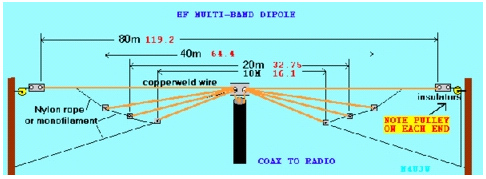
This kind of antenna allows the use of direct match to 50 ohm coax and should not need a tuner and will allow operation on mutibands with a little sweat equity on the construction side. Like I said in preamble, read up on this one, might fit your yard and your radio needs.

Not going to spend much more time on multi band antennas because once you have narrowed your focus as a newer ham you’re going to want to be louder than the guys using them, so next, a little time will be devoted to how to double your power out and increase that skip distance thing you memorized on your test!

Oh yeah; I GUARANTEE that either of the above antennas will work as well as or better than anything sold commercially for 10 times the price!

AND; I am aware it is a short list, counting on my antenna gurus reading this to jump in and expand!

But before someone else points out the obvious , let it be known that almost any piece of wire will get you on the air and be heard somewhere, but with a little homework you will enjoy designing something to fit in your backyard that will expand your horizons. During WW2 a little toy called a Slinky, yeah that thing, was used to successfully communicate on the battlefield! And hula hoops became super magnetic loops able to work the world at will, just kidding about that one.

SO YOU WANT TO BE LOUD WAY OUT THERE?

Well that’s going to take a little work if you are willing to play with some wire.

On the upper bands pretty much everyone has a commercial, expensive beam on some sort, on a tower, not to worry, the same can be done at nominal cost with wire. On 40 and below a wire gain antenna is the way to go and not hard to do. And once you get a little more into phased reversible wire arrays you will be truly competitive with most of the tower/ commercial store bought beam guys on ANY band.

1: YE GOOD OLD DIPOLE!

The most efficient, easy to build mono band antenna out there. Unless you are getting creamed in some contest with the big guns firing up their $20,000 stations, you will be heard, HOW?; because by hook or crook you figured out a way to get that sucker up in the air at around ½ WL on the band of your choice! If DX is your new found interest then broadside it to the NE/SW

If tight for room or lack of supports an inverted vee up as high as possible will give good results also.

Build your own and you will be amazed on any band with a dipole, especially with the emerging sunspots. The secret to DX is the lowering of your take off angle into the ionosphere and getting that first skip into the, direction/ area you’re chasing, a good high dipole can do it, other designs do it better however.

2: WIRE GAIN ANTENNAS:

It is beyond the scope of this article to explain the intricacies of multi element beam antennas like the one way up there on your neighbor’s tower.
Wire beams are relatively simple to build and extremely cheap! Commercial aluminum beams for any band are based on the property of the dipole.
By adding some correct length and spaced wires in front of, or behind, or both, of a dipole you have now focused the antenna in a narrower direction, another way to define gain.
Think of a flashlight as opposed to a candle and you will get the jist of focused energy in a specific direction.

Simple Two Element Wire Beam:

For shape reference only.

The addition of one wire 5% longer behind a dipole in the same plain will give you 3dbd of gain, in other words double your ERP; effective radiated power.
So that new 400 watt amp you saved up for will now have 800 watts going into the ionosphere. Oh yeah the extra power out works on receive also, adding an additional S unit and better signal to noise ratio for your hearing pleasure! You are focusing your transmitted signal in a smaller slice of the compass, helping diminish annoying signals off the side and the back.
This concept is applicable for every band from 2 meters to 160 meters; the spacing and between the two elements is subject to many variables and worth studying as is the possible shapes, quads, yagi, quagi etc.
The usual spacing between the wires for most gain is around .15WL.
If you have successfully built a dipole and remember the formula of 468/freq to achieve your ½ wl wire you are well on your way to using a little high school algebra to build your first beam antenna.

This process of free gain will open up an incredible arena of potential projects that will only be limited by your imagination and your commitment to studying the immutable laws of physics often contrary to a good portion of the advertisements we are all bombarded with everywhere.

Another worthy wire design is called a MOXON antenna with folded in elements that will fit where some wire beams will not. The moxon is a fun antenna and worth some serious study if you are plagued by loud stations behind you as it has very good front to back, meaning you will have an easier time hearing the station you are looking at.

Single Wire Gain Antennas:

About the only true single wire antenna that has 3db gain over a dipole is an EDZ, extended double zepp. These can be really long but if you have the room and tall enough supports this antenna will give you the same gain as a two element beam in two opposite directions. Mine has been up for years and has proven itself as the best narrow beam width single wire I have tried. Collinear antennas are a little shorter but have less gain so I stick with the EDZ.
Point being, as a new amateur either one might fit your needs so it’s worth the homework.

Getting Up In The Air:

The higher the band the smaller the antenna, nice little piece of physical law. Consider a 2 meter or a 10 meter wire beam built on the principals described above. Small enough to build and hang from any available tree and leave a string hanging from one corner to change directions, remember you built a directional beam, primitive maybe but mucho times better than the stub on your 2 meter hand held.

NO TREES ? Try something like below:

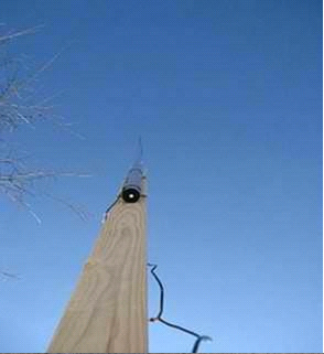
For an inverted vee or center of a dipole an easy to get 40 ft in the air pole for $50 is pictured. I use these things all the time in beam and vertical experiments They are 25ft extended and attached to a 2×4 and then to post holed 4×4, no concrete or help needed to install alone. Check fiberglass flag poles or Spider poles.

SUMMARY:

I suggest the best thing for a newly licensed ham to do is to get on the air and start chatting with people. You can ask them what antenna they are using and make your own deductions. Join a WAS net, like CCN or OMISS and see what you like or dislike about your present antenna. Determine if you have a favorite band that fits your interest and maybe upgrade to a mono band wire beam.

This article is a very cursory look at starter antennas and methods that will work great without killing your checkbook. Once you start down the road of designing and building your own antennas you will be addicted to this very important facet of our hobby and who knows, maybe you will writing a better article in the near future!

Tnx for reading,
N4JTE

Back to top^